Solar
This chapter describes how I tried to charge the lipo via solar cells.
caution
Read the reports about the autonomous testflights first and have a look inside the data analysis of these flights. I finished this milestone before moving on to the solar part.
Feasibility study#
Before I buy the cells, I wanted to be sure that powering the aircraft from the sun is feasible. The Duck doesn't have a big surface area suitable for mounting solar cells. To be honest, at the beginning of this project I didn't even plan to include automatic charging in addition to autonomy. So the shape of the aircraft is not really optimized to carry the largest number of solar cells possible. In fact, I think the wings have exactly the wrong dimensions to accommodate about 1.8 cells in width. I guess I will have to accept that the resting times on the lake will be a bit longer.
To calculate the power consumption, I need the total power consumed during the flight divided by the flight time.

Lets start by looking at the voltage and the current.
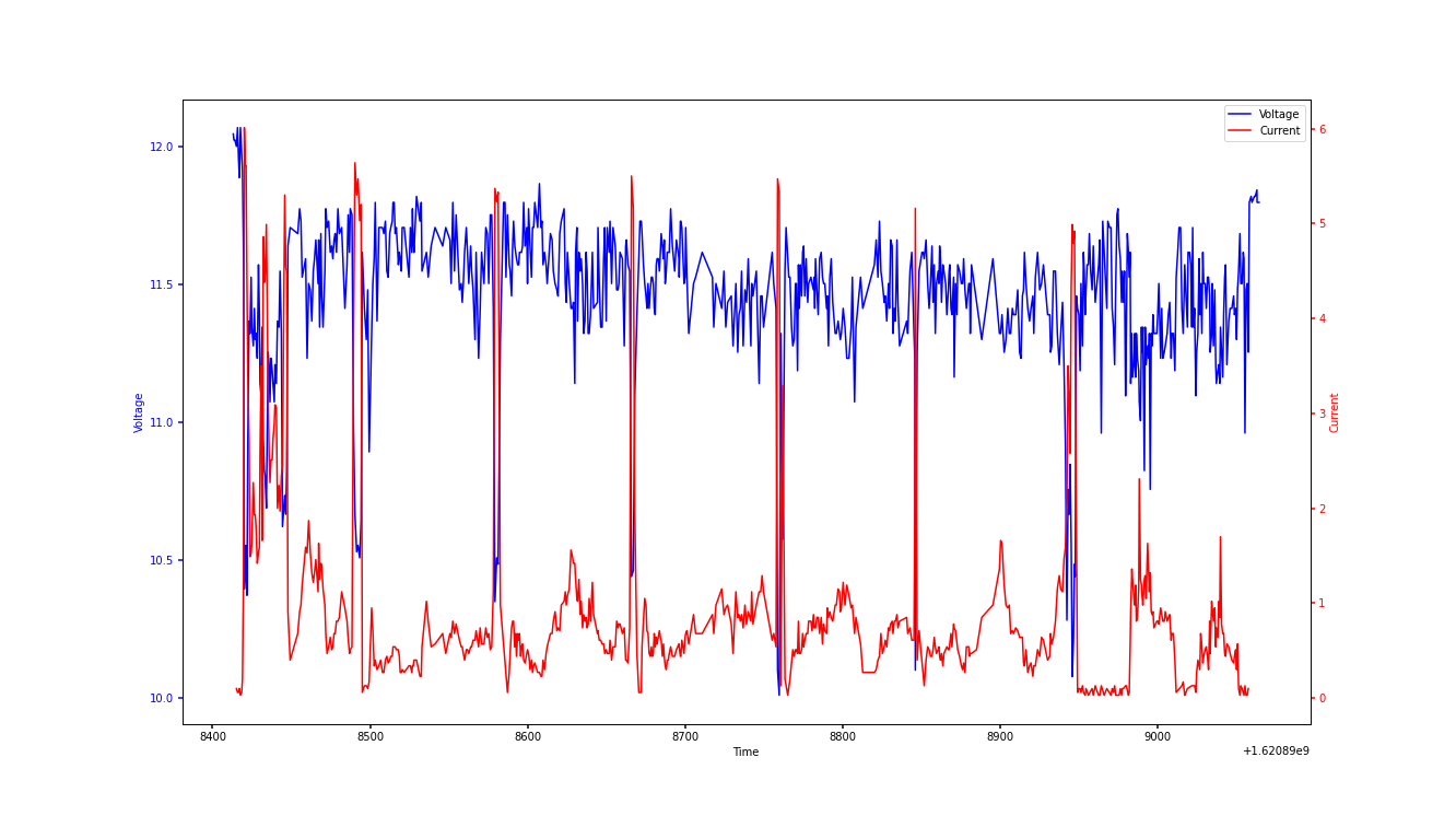
You can see that most of the time the current is between 0 and 1 amps. Integrating the the current over the time and averaging it by the time delta from start to finish in seconds gives us the average consumed power per second.
This results in ~0.48 amps. Adding the Raspberry Pi's consumption of 540 milliamps gives ~0.96 amps. If we assume an efficiency of 23% of the solar cells, 12.6 volts from the lipo, and 3.2 watts per cell, we get the following.
at least 17 cells.
Parts and wiring#
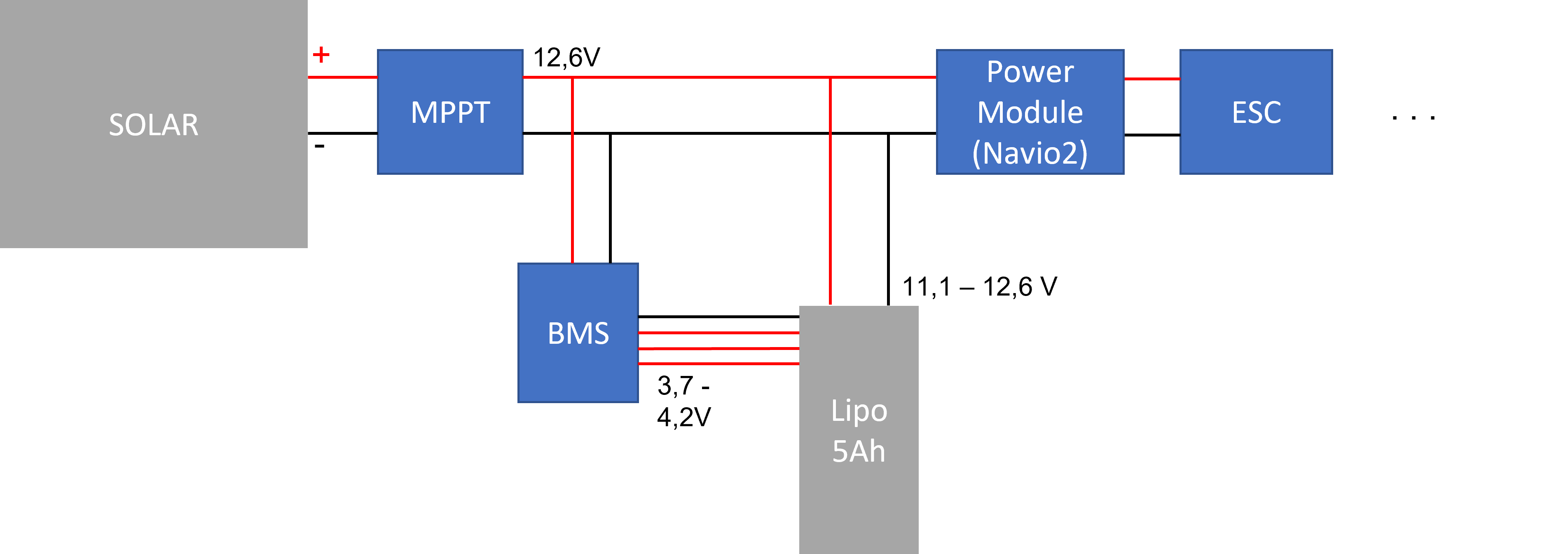
I need three essential components to enable solar charging. The most important component is of course the solar cells themselves. In order to use them efficiently and to maximize the wattage drawn, you need an MPPT (Maximum Power Point Tracker). The last part is the charge controller (BMS) for the lipo.
Solar Cells#
I needed solar cells that were not too large per piece, so that I could cover as much of the plane as possible with them.
In addition, they should have a certain flexibility so that I can attach them to the rounded shape of the wing.
After a short research and comparison with other solar planes, I found these 12,5x12,5 solar cells pretty fast.
MPPT#
The amount of sunlight hitting the solar panels varies greatly depending on the location of the aircraft, as well as latitude, solar field orientation, and time of year and day. For any given cell, there may be some shadowing over the course of the flight. In addition, the amount of energy generated by each solar cell depends on the irradiation and its temperature. Therefore, at any given time, it is necessary to determine the best specific operating point of the solar generator at which the greatest power is fed into the system. Through MPPT (Max Power Point Tracking), the solar power of the solar panels is optimally utilized and the flight time maximized.
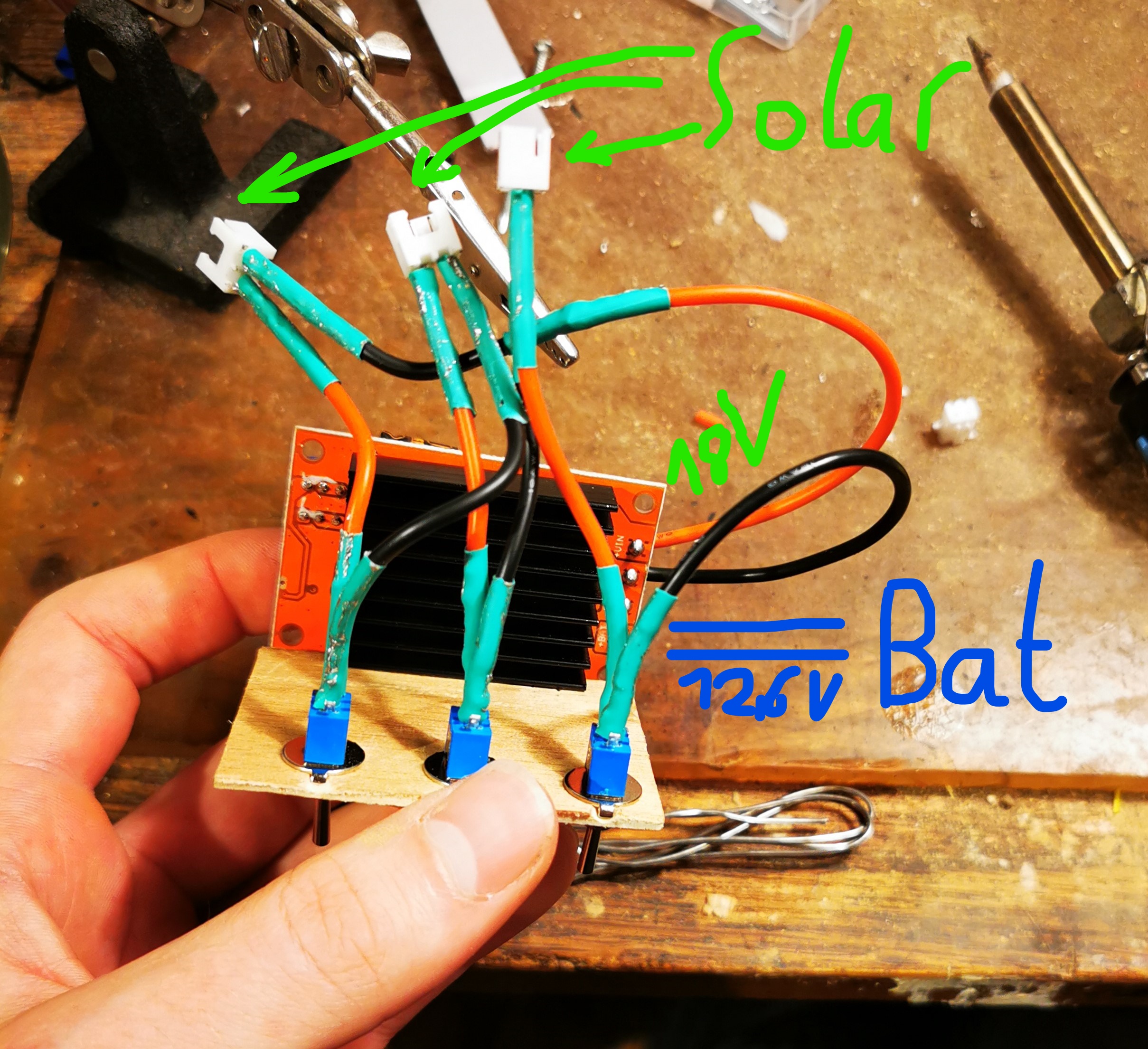
There are many different modules on the market. Many originally come from the marine industry, for example for solar modules of sailing ships. In the camping area you can also often find these modules. There are also YouTube videos in which such modules are used to charge a lipo. For me, these modules were a little too expensive with about 100 €. In addition, they are quite heavy and come with a case that is not needed for my application. I have therefore opted for a little more basic modules for about 10 €.
BMS#
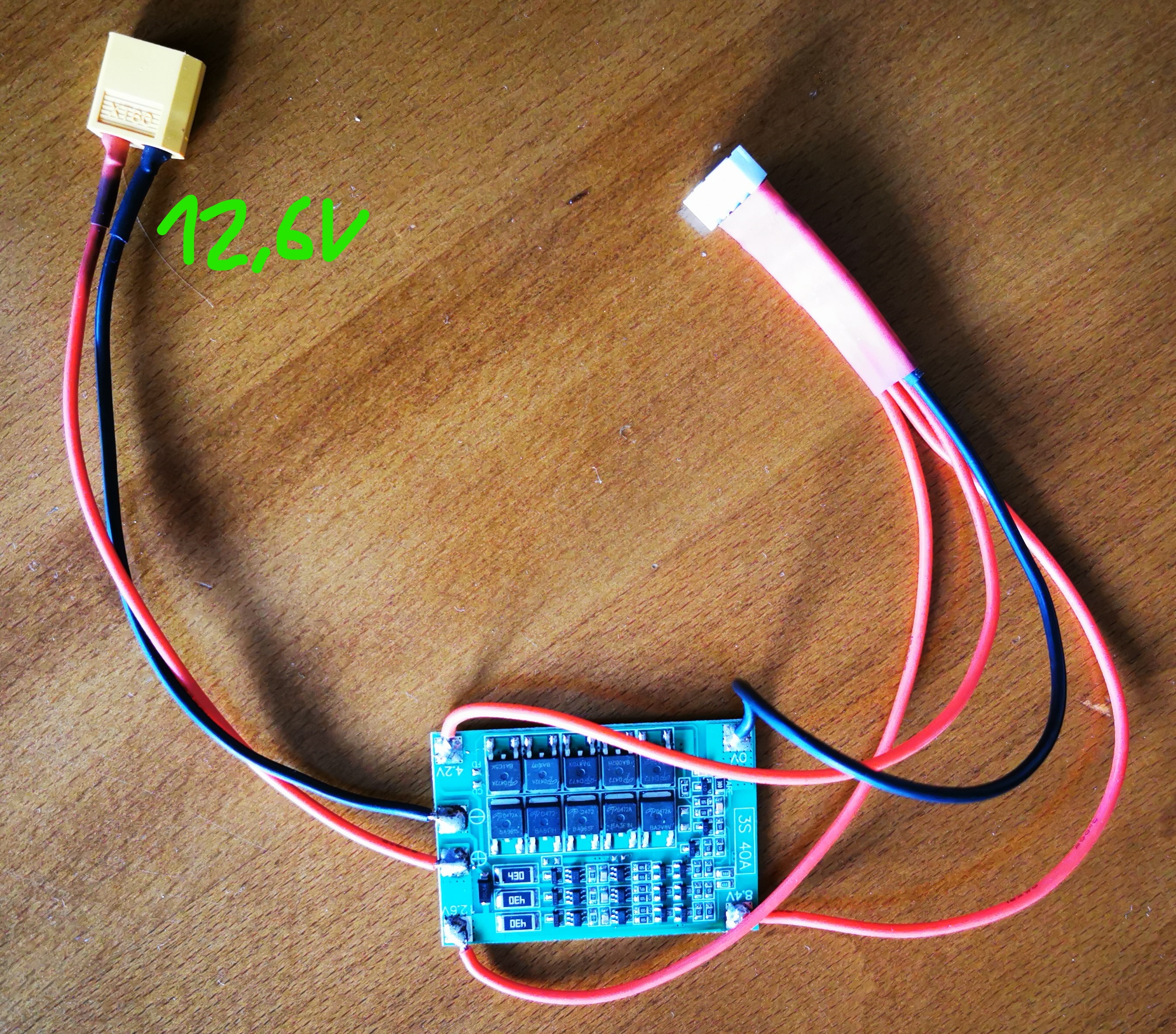
A battery management system (BMS) is an electronic circuit which is used to monitor, control and protect accumulators 1.
I use a 3 cell Lipo. Normally these batteries are charged by a balancer that adjusts the voltage of each cell individually. The nominal voltage is connected to the Lipo. In my case this is 12,6 Volts. Since the cells are connected in series, this charges each cell with 4,2 volts. If one cell is reaches this limit, a transistor within the BMS is activated and redirects the voltage from the cell to an internal resistor. Therefore the cell is not longer charged and the other cells will be charged until each transistor is activated.
Assumptions about BMS (pseudo knowledge)#
I am not an expert in this field. As far as I understood this is the way these chips work, the balancing takes place if the first cell reaches the limit of 4,2 volts. But what happens if you never charge them to 100% and the lipo is always around half full ? It might be possible that the voltage of the different cells drift apart over the time. I guess we will see if this happens...
Also I did not find anything about discharging the Lipo during charging with these boards. At least in theory the 12,6 Volts provided by the MPPT should be enough to power the Raspberry Pi, some servos and the motor on a low RPM. But what happens during the spikes that required >5 amps ? My guess is that if you connect everything as described in the wiring diagram, the lipo provides enough (temporary) current and the BMS simply does nothing. However, this is just some kind of "What else can possibly happen". I think I will simply risk the 10€ and try it.
Bringing it all together#
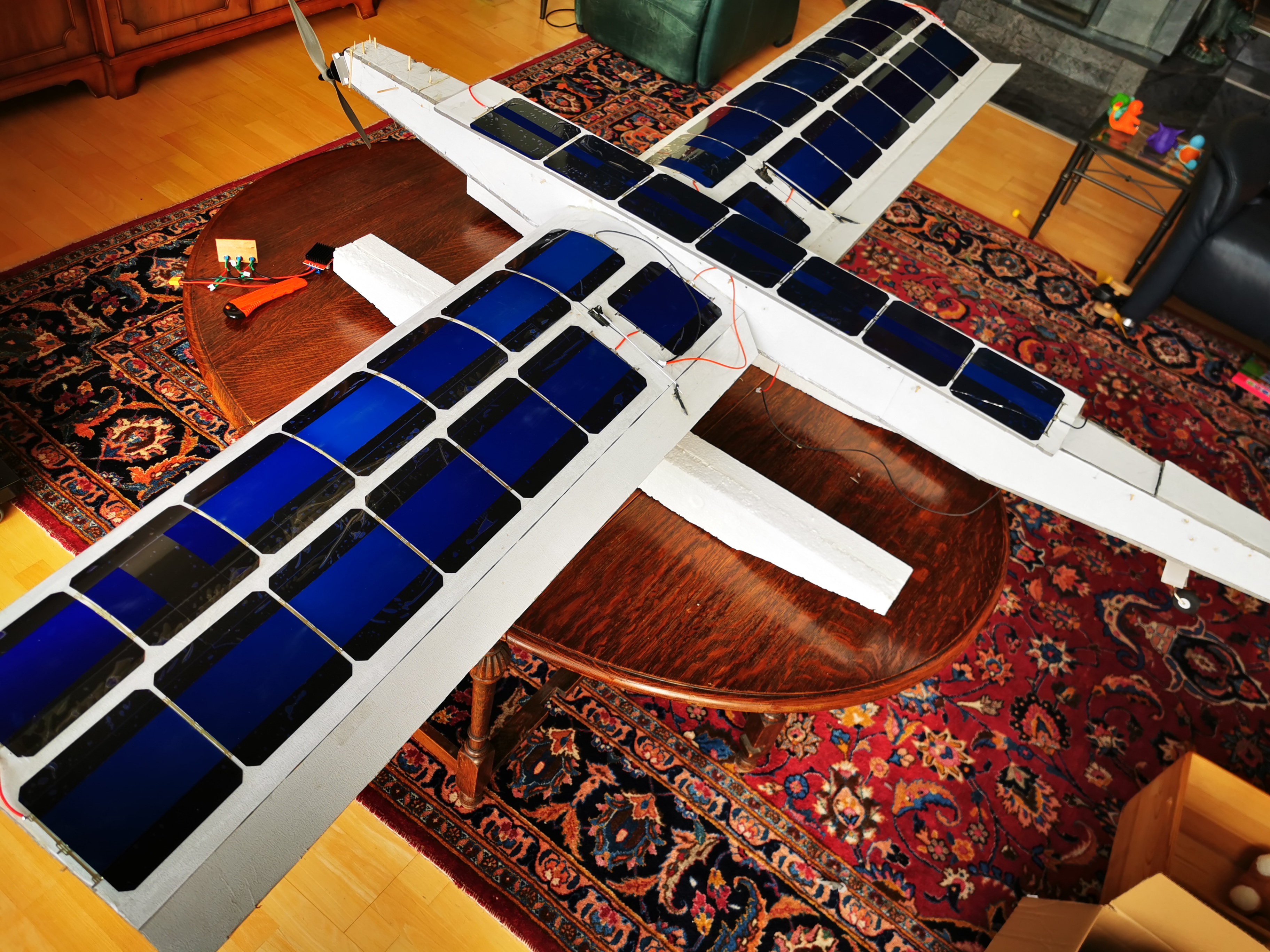
After the BMS and the solar module were completed, the solar cells had to be wired and the setup tested. I connected the solar modules to 3 chains of 7, 2 chains of 6 and two single solar cells each and placed them on the wings. After everything was wired, I taped the cells to the wing. Each wing has two chains of 7, one divided into a chain of 6 and a single.
The fuselage carries a 7 chain.
caution
Test before you attach the solar cells to the aircraft to make sure they are all working.
In retrospect, it turned out that three solar cells were defective and did not provide any power. Fortunately, they do not interrupt the circuit, so I can accept in the short term that I am missing 3.