Drive
Mounting#
When I started building the Duck, the plan was to mount the motor at the front of the plane. A landing gear was not mounted at that time, so the rotor could not rotate freely when lying on the ground. If you try to land in this setup, it would inevitably cause the rotor to break or damage the front of the airplane.
note
Unfortunately, I learned this obvious fact after the nose broke off during the first test flight.
There was another problem: The weight of the plane was not centered between the wings. It was too heavy in the back. The lipo could be stored very far forward, which solved the problem a bit. To allow for a higher payload in the long run and not to store everything in the front, another solution was needed.
The not-so-solid engine made of XPS#
I wanted to move the center of gravity forward and the engine higher so that the propeller could no longer touch the ground. Therefore, I built an engine, which I wanted to simply mount on the plane. One enginge per wing would have been cooler, but I only had one motor.
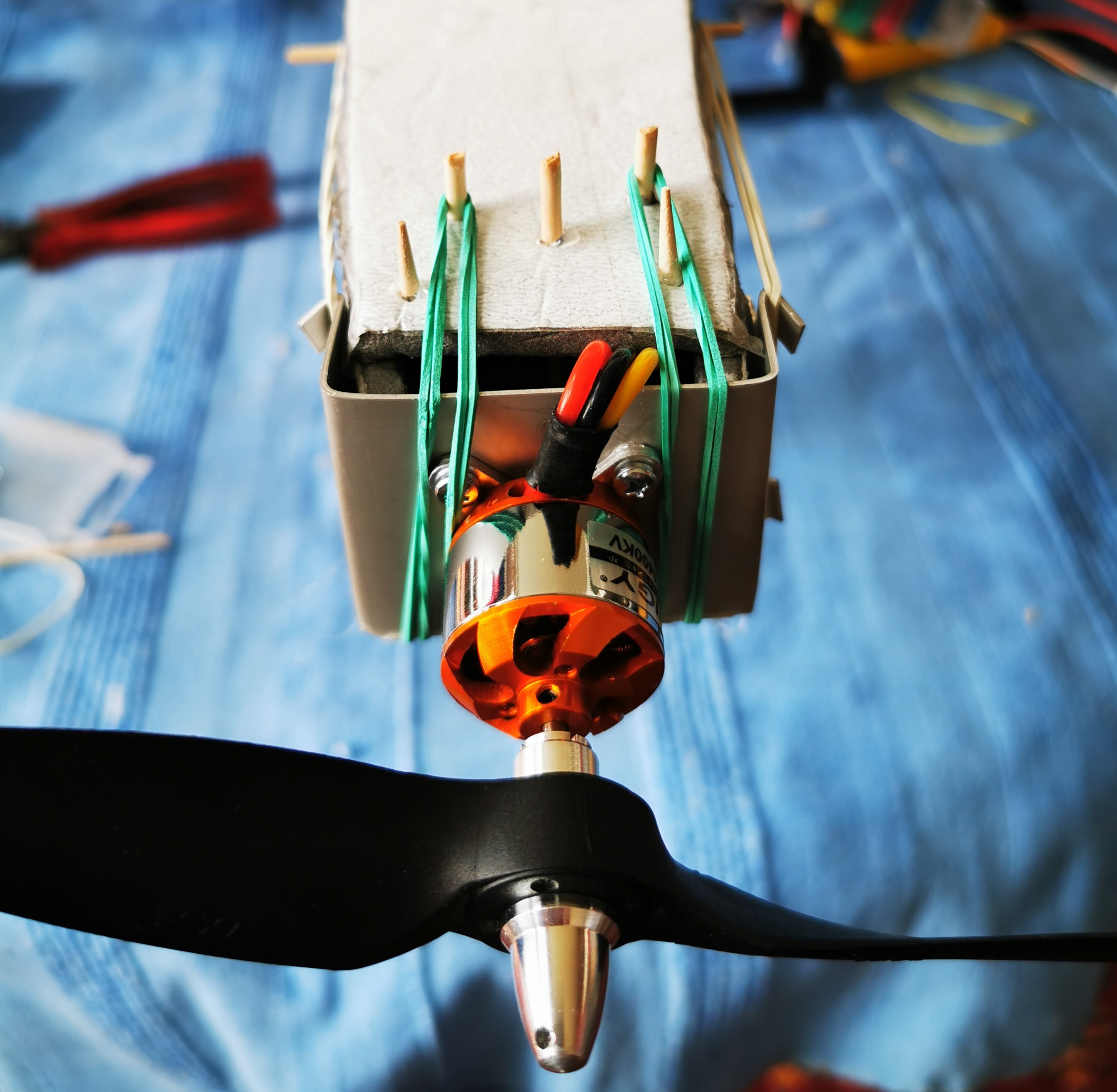
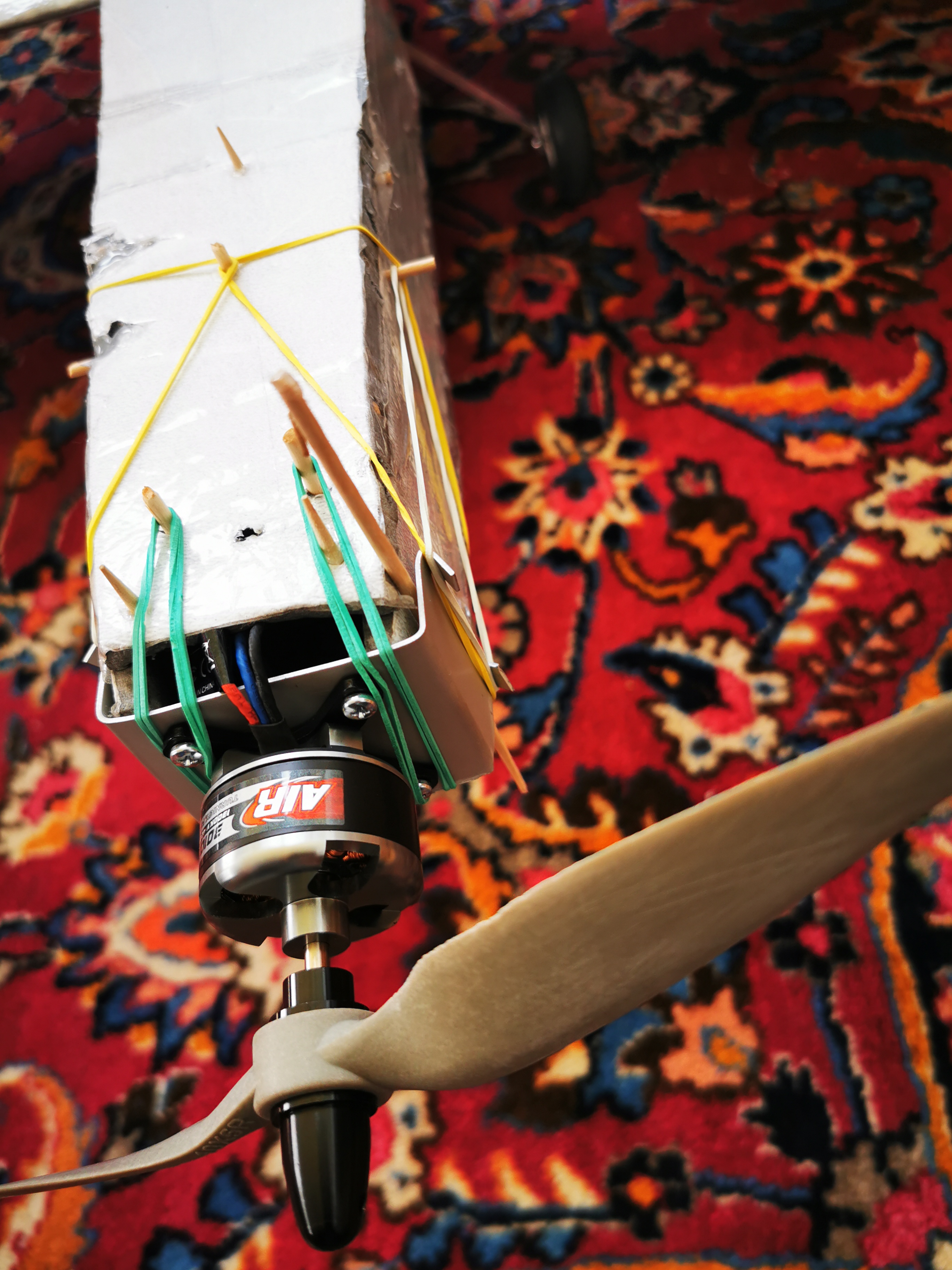
So I started to build a frame out of XPS, which was pretty stable. However, it turns out that it is not a good idea to use screws to attach the motor to the XPS.
I simply attached the engine to the top of the plane with a couple of wooden skews and hot glue. In order to be able to remove the engine if necessary, I decided to connect the engine to the fuselage with rubber bands instead of hot glue. At the first start with this setup, it was immediately clear that the engine was not working as I had hoped. In fact it was performing so bad that the plane nearly crashed. The vibration destroyed the XPS and the motor came loose. In this process, it tore off the cables and disturbed parts of the nose with the propeller. Back to the drawing board...
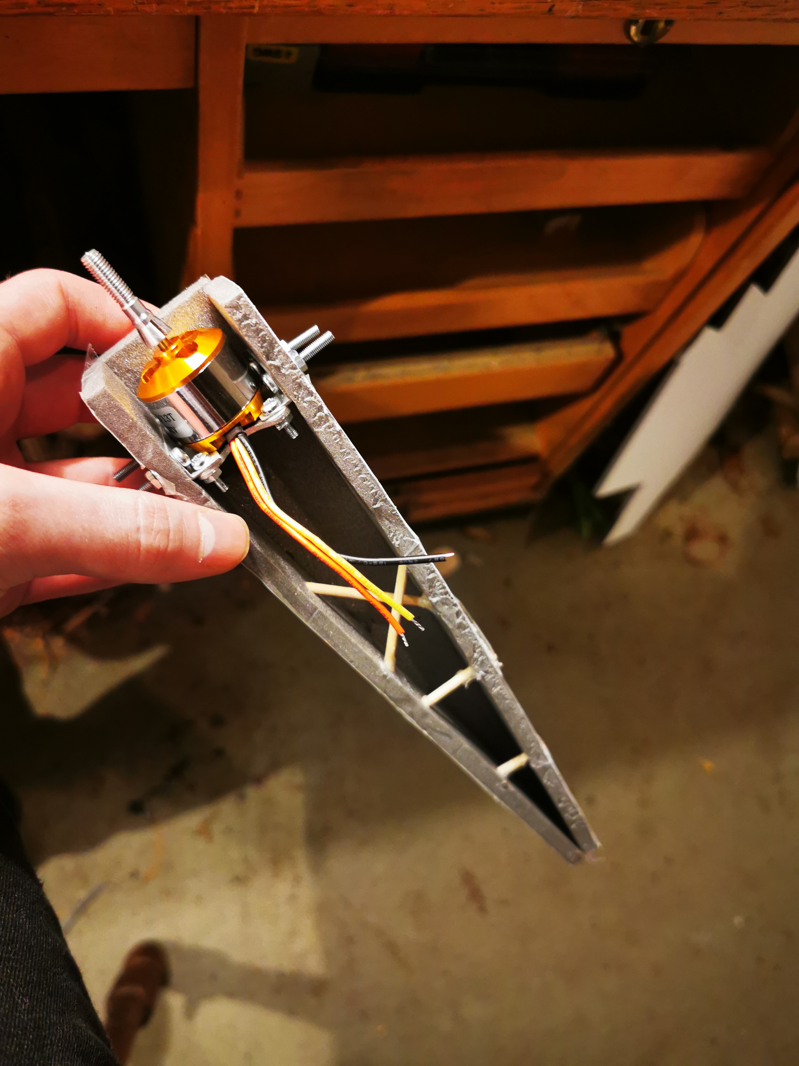
Rubber band#
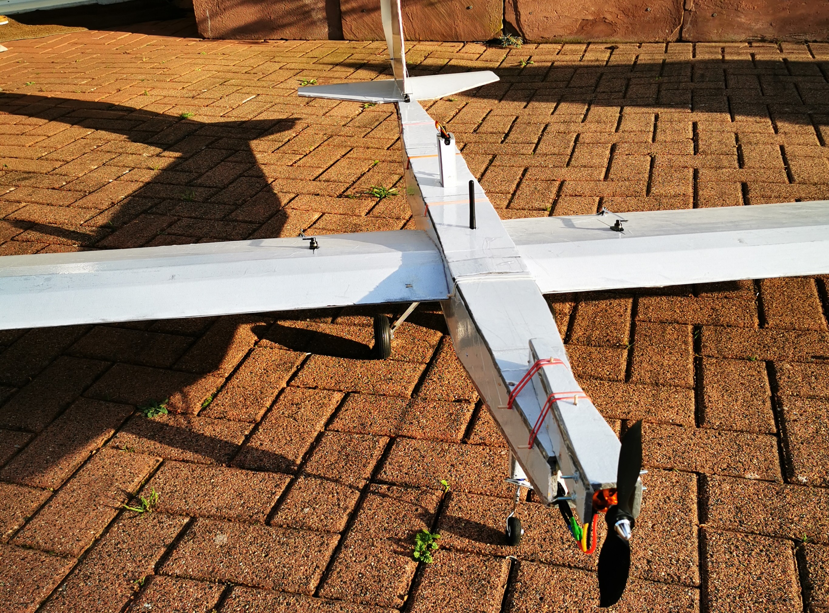
I have learned my lesson. The vibration of the motor is not compatible with foam. I had to find a solution to fix the motor safely and to construct a connection to the airplane that allows vibrations or possibly even dampens them. I didn't want to use screws or glue, so I cut a rectangular piece out of an aluminum plate and bent the two ends 90 degrees. I attached the motor to this plate and pushed back a small strip at all ends. The plate including the motor could be attached to the plane with rubber bands.
A test flight showed that although there are still vibrations that are transmitted to the entire aircraft, the engine is secure. I hope this does not affect the gyro.
After the first testflight , i realized that the vibration did not longer destroy the foamboard. However, this time the screws connecting the motor with the metal came loose, causing the motor to fall off. After a few test runs on the ground, I noticed that at a certain speed, the mounting, which was attached with rubber bands, began to wobble back and forth. It had too much slack in the horizontal axis. I tightend the aluminum plate to the XPS, by pushing a wooden stick between the aluminium plate and the XPS .
Motors#
At the beginning I startet with a cheap motor from turnigy. After the first crash with the XPS motor, I bought two more motors. One low KV, high torque motor and one powerfull motor with roughly the same KV.
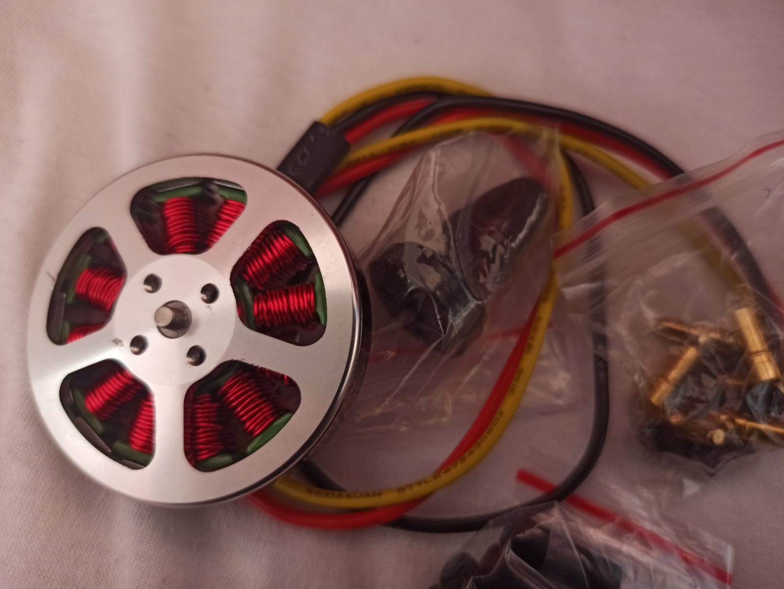
Stats#
| Turnigy D2826-10 1400kv | Turnigy L3010B-1300 | 5010 - 360 KV | |
|---|---|---|---|
| Size | 28mm x 28mm | 37mm x 27mm | 50mm x 10 mm |
| Weight | 50g | 88g | ? |
| Kv | 1400 rpm/V | 1300 rpm/V | 360 rpm/V |
| Voltage | 2S~3S (7.4v to 11.1v) | 11,1 V | 11,1 V |
| Watts | 205w | 420W | ~305W |
| Current | max. 40A | max. 60A | max. 40A |
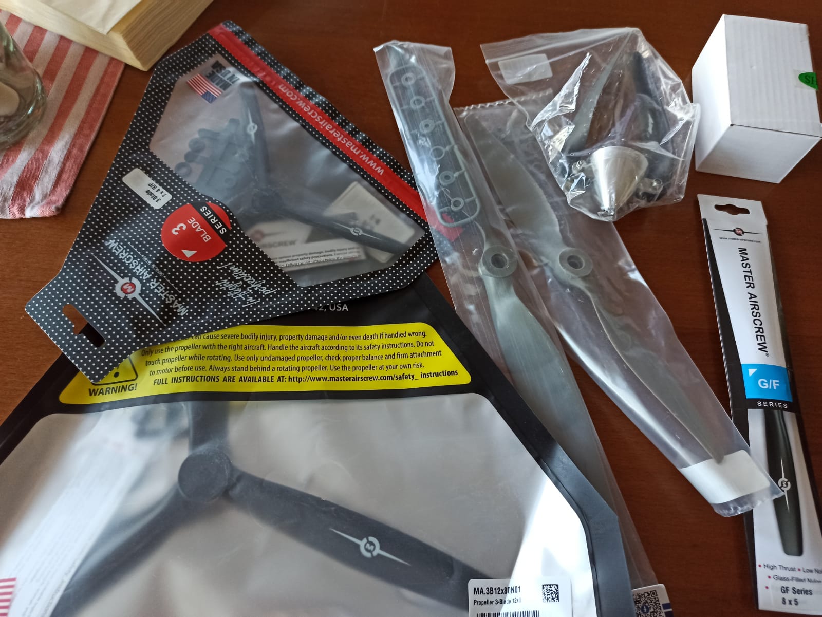
On the second test flight, I choose the low KV motor to save energy and maximize flight time. This motor does not have enough thrust with a 12x8 3-blade propeller. I installed the 420W motor so I wouldn't have to worry about not having enough thrust.